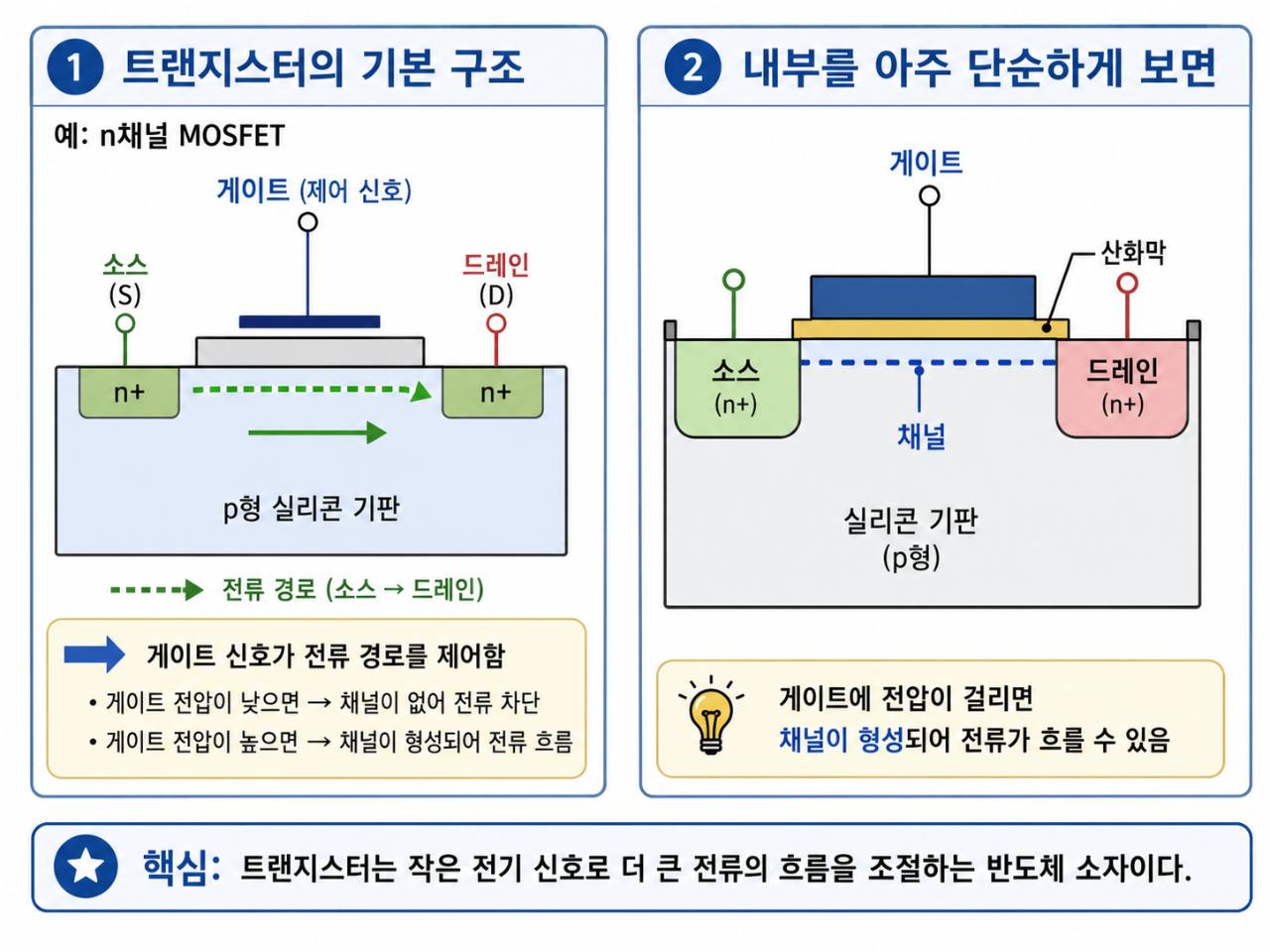
This image is useful as a first visual model of an enhancement-mode n-channel MOSFET. It should be treated as a simplified MOSFET diagram, not as a general diagram of every transistor.
Accuracy Verdict
The main idea is correct: an n-channel MOSFET has source and drain regions, a gate separated from the semiconductor by an oxide insulator, and a p-type body or substrate. A sufficient positive gate-to-source voltage can induce an n-type channel under the gate. Once that channel exists and a drain-source voltage is applied through an external circuit, carriers can move between source and drain.
The image is accurate enough for the durable learning question:
How can a gate voltage make a current path possible without the gate itself being the main current path?
Important Caveats
- The diagram describes a MOSFET, not every transistor. A BJT has a different structure and a different control mechanism.
- “High gate voltage” should mean gate-to-source voltage above the relevant threshold, not merely a high absolute voltage at the gate.
- A channel being formed does not by itself supply current. Current also needs a drain-source voltage and a complete external circuit.
- In an n-channel MOSFET, the mobile channel carriers are electrons. Under the common bias where the drain is at a higher potential than the source, electrons move source-to-drain, while conventional circuit current is described drain-to-source. The image’s source-to-drain arrow is best read as carrier movement or current-path simplification, not as the conventional current direction.
- A real MOSFET can include a body terminal, parasitic capacitances, leakage, a body diode, device limits, and geometry that does not look like this planar first model.
Durable Understanding
The gate does not open a mechanical door. It changes the electric field near the semiconductor surface. Because the gate is separated from the semiconductor by oxide, the gate can control the channel electrostatically instead of becoming the main source-drain current path.
For an enhancement-mode n-channel MOSFET, the channel is not a permanently available wire between source and drain. The useful first model is:
Gate-to-source voltage controls whether a conductive channel is available between source and drain.
That is why MOSFETs are first understood as voltage-controlled devices.
How To Use The Image
Use the image to remember these ideas:
- source and drain regions are doped differently from the body
- the gate sits above an insulating oxide layer
- the channel forms near the surface under the gate
- the gate controls the availability of the source-drain path
Do not use the image to infer these stronger claims:
- all transistors have MOSFET structure
- source-to-drain is always the conventional current direction
- the simplified drawing is the exact geometry of every modern MOSFET
- gate voltage alone creates useful circuit current without the rest of the circuit
Verification Basis
- MIT OpenCourseWare 6.012 Lecture 11, MOSFETs II: Large Signal Models supports the enhancement-mode n-channel MOSFET framing and the use of gate-source and drain-source voltages in the device model.
- MIT OpenCourseWare 6.012 Lecture 12, Sub-threshold MOSFET Operation supports the induced n-type channel model and the distinction between electron movement and circuit-current convention.
Connected Reading
Extends
- MOSFET Terminals: Gate, Source, Drain, and Body. Preserves a visual source note for the MOSFET structure explained there.